When it comes to 3D printing, you have a choice of the normal filaments: PLA or ABS. Basically ou can print PLA filaments (not ABS) onto rough surfaces, in my case a glass plate with some hair spray (because i’m worth it,) or you can print both onto heated surfaces. This heated surface or heatbed (not the kind you sleep in) allows the filament to stick to the printing surface at the start of printing and also stops the filaments from cooling to quickly and warping. Exact temperaturs are usually given by the filament manufacturer.
Guess it’s already time to upgrade to a heated bed (good thing i already ordered the parts)
The Research:
RepRap.org approved heatbeds and a bit more info on them: http://reprap.org/wiki/PCB_Heatbed.
From what I have read, it is a good idea to go for the one that a) fits your machine, b) is the most advanced revision.
IT is a good idea to provide a bit of insulation on the base of the heatbed to make the heat conversion a little more economical, for this simple cork tiles can be used.
Be aware that a heatbed will also up your PSU current requirement by around 10A so if you kit came with a small 8A laptop PSU, it’s time to upgrade.
The Hardware:
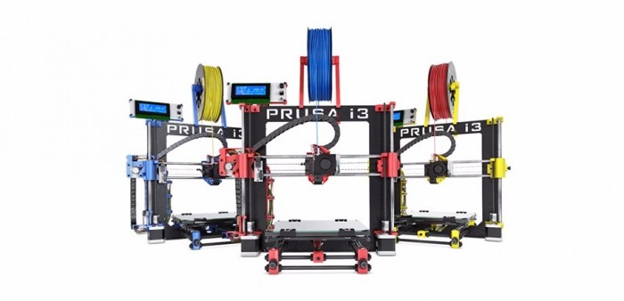
Heatbed MK2a, including leds and a 100 kohm thermistor from Think3DPrint3D for a very reasonable price
- Heatbed: MK2a
- Thermistor: EPCOS B57560G104F
12V DC 30A Regulated Switching Power Supply from Amazon
300 x 300 x 3 mm Cork tiles from Amazon
Hardware installation:
Stock Bed:
The first step is to understand the mechanics of the stock bed.
There is basically a sheet of glass that is bull-dog clipped to an acrylic base.
The acrylic base is held in place by a sprung base made by 4x M3 screws, and 4x compressions springs.
This basically allows you to tighten the M3 screws and the bed will always try and push up to the highest point, this makes it easy to level the bed out by adjusting one or all of the screws.
Upgrade:
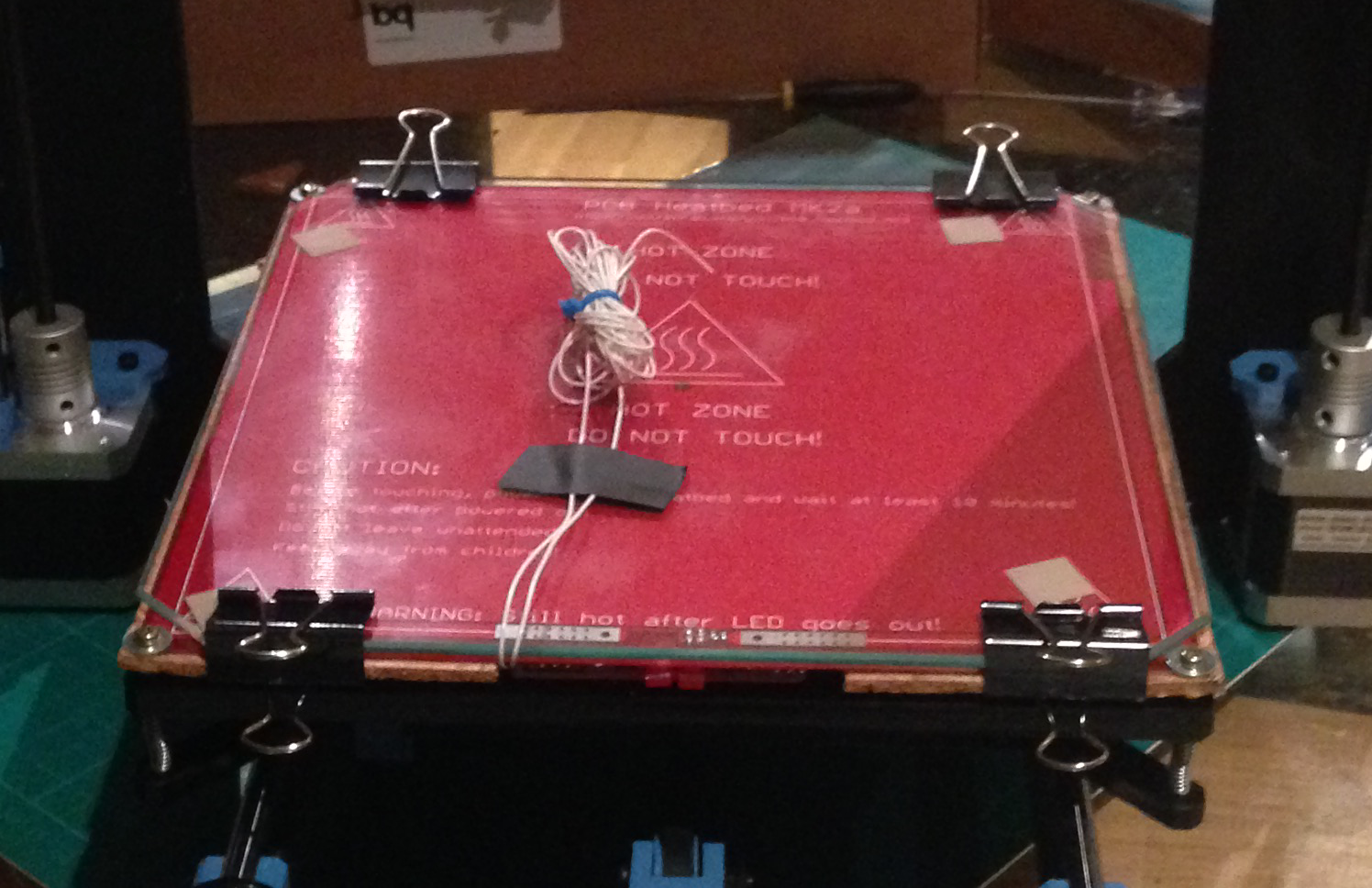
The upgrade literally sandwiches the heatbed between the glass and the acrylic+double layer of cork.
The cork, the heatbed and the acrylic are all held in place by the longer screws.
The glass is then clipped to the heatbed and 1st cork layer to secure it in place.
The heatbed also ahs a small hole in the center, this is the home of the Thermistor that then runs underneath the first layer of cork and out to the front of the printer.
Hardware Additions:
- Washer: 3M
- Heatbed: MK2a
- Thermistor: B57560G104F 100 Kohm
- Cork tile: cut to size by drawing round acrylic board
- Nuts M4: this is to allow the screws to slide through.
- Cork Tile: cut to support middle of glass but allow Thermistor to be put in place.
- Longer screws: M3
- Longer M3 screw for Z-aixs stop: This stops the print head at just the right time.
Wiring:
Wired heatbed to D8 and Thermistor to T1 connections on the RAMPS 1.4 following instructions on http://reprap.org/wiki/RAMPS_1.4
Testing:
Having selected a little model from thingverse.com it was time to test that heatbed. I started the print and saw the LCD display change to “Bed Heating” and then nothing…. no rise in temperature…. whyyyyyyyyyyyyyyyyyy!
After a bit of reading it became apparent that the firmware was not configured properly for the custom setup!
What do?
FWTFW!
(Answers on a postcard)
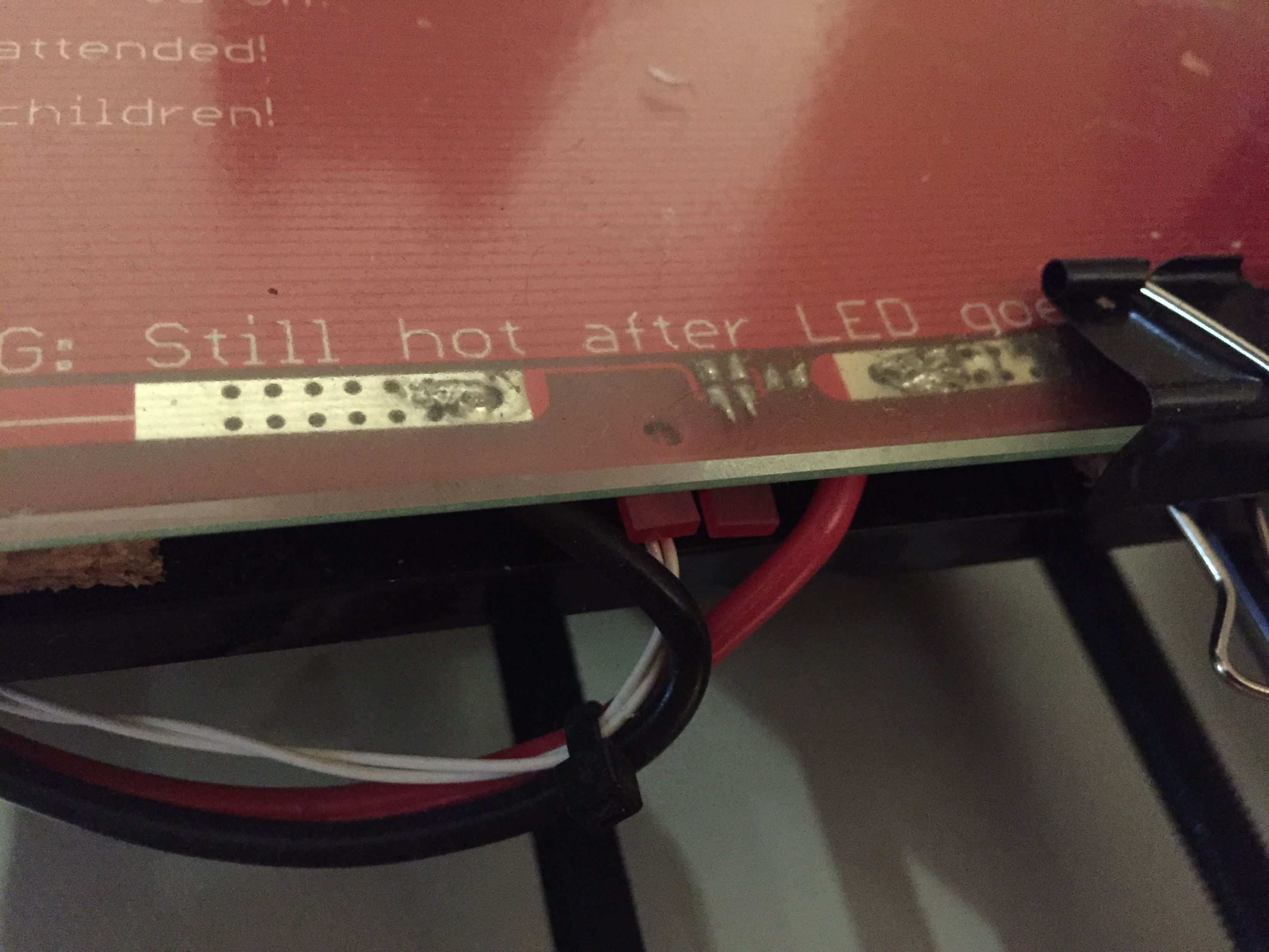
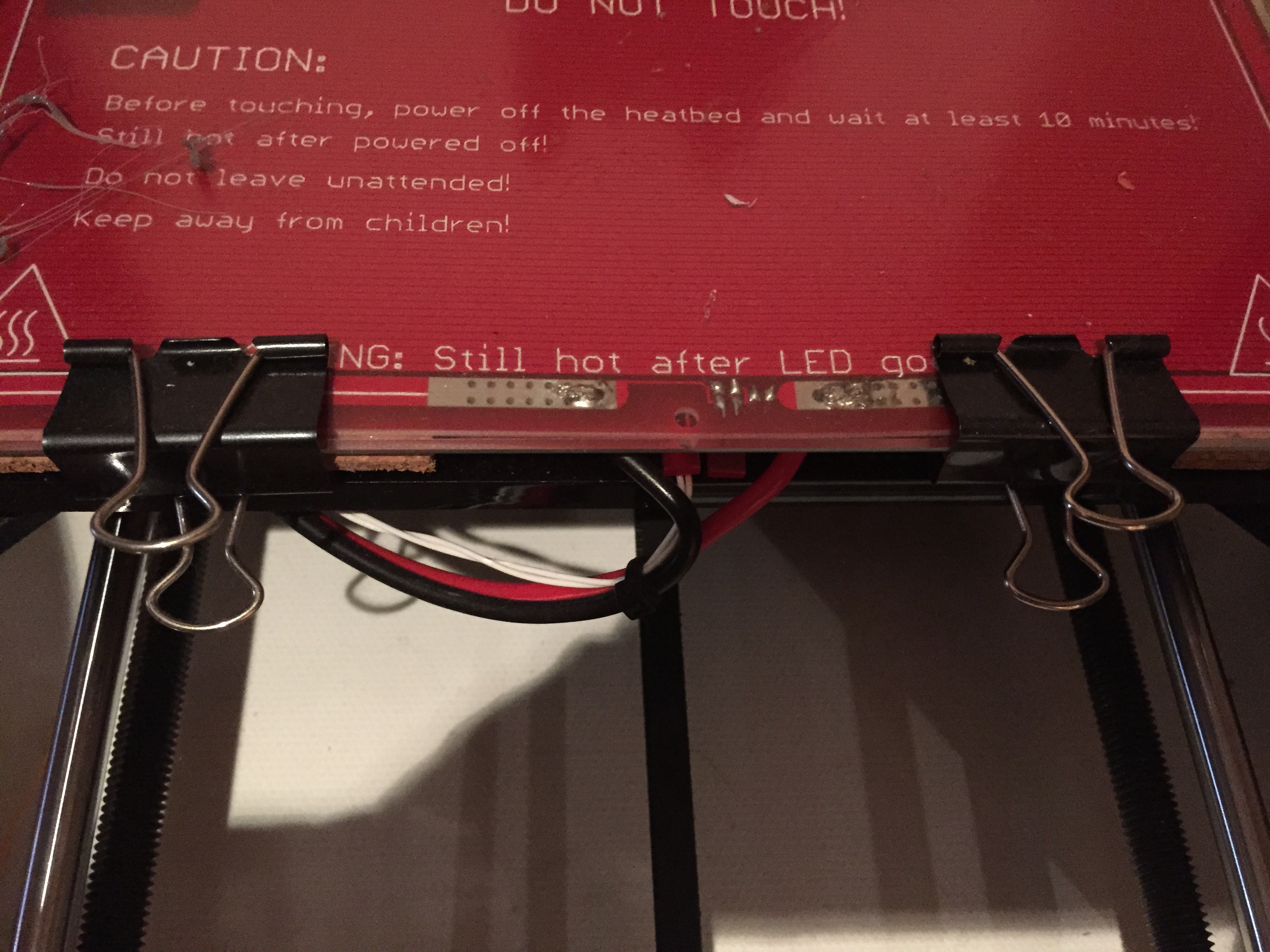
Hi… Do you have any “special” trick on how to solder the power cable to the heatbed an still being able to place the glass over it?
Thanks in advance
Pedro,
No real trick to it. I Just kept as much as I could downward facing then used clips to ensure it the heatbed makes contact with the glass.
I have updated the post with more images of the connections.
Hope it helps